Introduction
The power generation industry can be regarded as the cornerstone of modern civilization. Modern power generation takes a variety of forms as will be seen in the below article. It will be evident that the magnitude of this industry is such that one article cannot cover all of its details.
The top 10 electricity consumers are China, the USA, India, Russia, Japan, Brazil, South Korea, Canada, Germany, France, and Saudi Arabia. China consumes around 7805 terawatt-hours of electricity which is almost 2 times that the USA consumes and around 5.5 times that of India. (as of 2021, Reference https://www.statista.com/statistics/267081/electricity-consumption-in-selected-countries-worldwide/)
As of 2021, 63% of total world’s electricity is produced from Fossil fuel- Coal-37%, Gas-23%, and Oil- 3%, whereas the remaining 37% is produced by low-carbon sources such as Nuclear – 10%, Hydro- 16%, Wind-5%, Solar-3%, and 4% other renewables. (All percentages are approximate for reference, this % may change from time to time as per conditions)
Industry by Segmentation
The industry can be considered to comprise several segments:
1. Fossil-fuelled Power Plant
2. Nuclear Power Plant
3. Internal Combustion Power Plant
4. Renewable Energy Sources
Process Overview
1. Fossil-Fuelled Power Plants
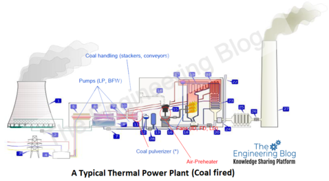
Fossil fuel power plants generate electricity by burning fossil fuel to produce steam, which powers a turbine to drive the generator. Typically the boilers are fuelled by:
Coal – Using coal means equipment is required to unload, convey, weigh, and feed the fuel to the boilers. Additional machinery is also required to deal with the waste products from combustion (ash).

Oil – This fuel requires storage, pumping, and heating equipment.
Gas – These stations have become more numerous in recent years in line with the improved availability of natural gas resources.
A number of fans may be employed to ensure the efficiency of the combustion process. Some are used to deliver air to the burners, which are referred to as forced draft (FD) fans. Other fans, called induced draft (ID) fans, are employed to draw the combustion gases through the boiler to the discharge stack, by way of various emission control systems.
Irrespective of the fuel source, the boiler water needs to be carefully conditioned. Water treatment plants might include filtering, demineralization, softening, and evaporators. The processed water is then passed through a de-aeration process to remove the last traces of oxygen and non-condensable gases, after which, boiler feed pumps take the water to the boilers.
Typically, a modern station employs a sophisticated and centralized control system with advanced computer and software systems to regulate and coordinate fuel feed, air supply, and water flow to optimize plant performance (to achieve maximum efficiency)
High-pressure steam from the boilers is used to drive the turbines, which in turn drives the generator. One turbine has a condenser cooled by river water (or other source). The other turbine operates non-condensing and supplies low-pressure steam that is used to pre-heat the feed water, aiding efficiency.
The plant is usually monitored from a central control room, which is heavily instrumented.
Effective condition monitoring of steam turbines usually includes the measurement of a number of parameters not relevant to other process machinery. Typically, turbines utilize plain bearings, which require the use of non-contact sensors (also called eddy current probes) to measure the shaft vibration relative to the bearing. Additional sensors are used to monitor the expansion of various parts of the turbine as it warms from cold to normal operating temperatures. A permanently installed, online monitoring system is used to measure these (and other parameters). Such systems are sometimes referred to as turbovisory systems to differentiate them from ordinary condition monitoring packages.
2. Nuclear Power Plants
Nuclear power plants have become a popular choice, however, The radiation hazard results in a number of unique requirements. Examples include:
> Development of transportable balancing machines capable of handling large, radioactive rotors.
> Greater use of online monitoring to enhance safety and eliminate the need for patrol inspection.
Development of special sensors and cabling designed to operate successfully in radioactive environment.
In reality, there are a number of types of nuclear power stations. All employ steam turbines to drive the generators but they differ in the means by which the required steam is generated.

2.1 Pressurized Water Reactors (PWR)
These are the most common type in current use. Powerful pumps are employed to pump water from the reactor core into very large steam generators. This is done to separate the reactor cooling water, which may be radioactive, from the secondary team circuit, which feeds the turbine generators.
2.2 Advanced Gas-cooled reactor (AGR)
These employ carbon dioxide to cool the reactor core. Large fans (gas circulators) drive the gas around the core to remove heat. The hot gas is then used to raise steam.
2.3 Boiling Water Reactor (BWR)
These are also in fairly wide use. They employ a reactor core somewhat larger than that of a PWR. The characteristic of this design is that accidental loss of cooling water results in the reaction shutting itself down. This makes the design inherently safer and eliminates the need for backup cooling systems. The large containment domes and steam generators used in PWRs are not needed so this type of station is less expensive to build.
3. Internal Combustion
Internal combustion engines, typically gas turbines or diesel engines, power some generators. Large diesel engines (similar to ship engines) are commonly employed for power generation in the building services industry. Many large data processing facilities (e.g. those associated with the banking industry) are heavy consumers that require guaranteed supplies. To satisfy this requirement, they often generate their own power from large diesel engines.
Similar barge-mounted generation sets situated just offshore are also employed in some parts of the world, as they provide a relatively low-cost means of generation in comparison with the capital cost of building a land-based power station.
4. Cogeneration
Cogeneration is the simultaneous production of heat and power in a single thermodynamic process. Almost all cogeneration utilizes hot air and steam for the process fluid, although certain types of fuel cells also cogenerate.
Cogeneration then, by definition, requires the production and use of steam or hot water for a secondary purpose (i.e. heating, production process, etc.) in addition to the generation of electricity.
This system is efficient because the thermal energy of the steam or hot water taken off of the generating system can be used down to lower temperatures than would be possible in the generation process.
It is also clear from the definition that he term “cogeneration” is not specific to either combustion turbine generation or steam turbine generation. Either type of prime mover can be used to “cogenerate.”
In cogeneration plants residual steam or hot water (from the power generation system) may be used within the process or for heating. Such installations are referred to as Combined Heat & Power (CHP) plants. These are becoming increasingly common as large sites seek to become self-sufficient in energy production to better control energy costs and guaranteed supply. Figure 3 below depicts a simple example of a CHP installation where residual heat from steam turbine power generation is employed in a process.

4.4.1 Combined Cycle
One special case of cogeneration arises when the hot exhaust from a gas turbine-powered generator is passed through a heat recovery steam generator, which provides high-pressure steam to a second, steam turbine-powered generator. Such systems are referred to as “combined cycle” plants. An example of such a configuration is given below.
Combined cycle plants are thermally very efficient, and have become increasingly common over recent years in regions of the industrialized world that enjoy ready availability of natural gas supplies.

4.5 Renewable Energy Sources
Concerns regarding resource depletion and environmental effects have, in recent years, led to increased interest in power generation using natural and renewable sources of energy.
4.5.1 Hydroelectric Power
Flowing water has long been used as a source of power. The first hydroelectric power plant was built in Appleton, Wisconsin in 1882 to provide power to two paper mills and a home.
In recent years, the economics of hydroelectric generation has been examined more closely, as issues relating to the conservation of water resources, irrigation requirements, and flood control are more significant. Nevertheless, this method of power generation continues to be a major sector of the industry.
The hydroelectric generator converts the power of flowing water into electricity. The quantity of electricity generated is essentially a function of the volume of water flow, and the amount of head (the vertical drop between the surface of the water source, and the power turbine).
A typical hydropower station comprises of a dam, penstocks (pipes), a powerhouse, and an electrical substation. The water used in hydroelectric plants does not require the careful conditioning required for efficient steam generation. Most hydroelectric power plants employ only one-way water flow. These are referred to as conventional plants, of which there are two types:
Run of river plants uses little stored water to provide the flow required by the turbines. Their output may fluctuate due to weather (particularly seasonal) changes.
Storage Plants utilize large dams that allow enough water to be stored to offset seasonal fluctuations in water flow.
In some areas, pumped storage schemes operate to provide low-cost peaking capacity. A combined pumped storage plant employs available power capacity during off-peak periods to pump water to a storage reservoir. Then, during periods of high demand, the stored water is released and used to drive a turbine. A typical pumped storage application is outlined below.
The design of the hydro turbine may be modified to allow it to function as a pump to return water to the storage lake. Turbines used in these applications may resemble conventional hydroelectric turbines, but they incorporate a number of detail differences. Typically these include:
A design that allows units to operate in both directions of rotation.
Ability to operate as a motor and generator.
Combination of the adjustable guide vanes required for turbine operation, with the larger impeller required for pumping.
4.5.2 Biomass
Biomass energy utilizes waste and animal material as its power source. Primarily, it utilizes the waste products from forestry and agriculture, although some fast-growing crops are cultivated specifically for this market. The utilization of biomass technology within the power generation industry varies considerably from country to country. Biomass is converted to electricity in a number of ways such as:
Direct Combustion is the direct burning of biomass fuel to produce heat, which is used to raise steam.
Gasification involves heating the biomass to convert it to a combustible gas, which can then be used to power a gas engine or a gas turbine within a CHP plant.
Pyrolysis involves the chemical conversion of biomass into pyrolysis oil. This is typically less bulky than solid biomass, making it easier to store and transport. It is burned to produce steam.
In some cases, biomass fuel is used to supplement fossil fuels within a conventional power station. This is referred to as co-firing.
Municipal Solid Waste (MSW) is also commonly employed as a power source. In the United States, for example, 3000 MW capacity currently exists. This may be by direct combustion, or by utilizing gases that build up within a landfill operation.
4.5.3. Geothermal Power Sources
Geothermal Plants also employ a steam turbine as the prime mover. The required steam is generated by natural hot water or steam that derives its energy from heat found in rocks or fluids at various depths beneath the surface of the earth. This energy is extracted by drilling and/or pumping.
4.5.4. Solar Power
Photovoltaic cells are used to convert incident light directly into electricity. Solar thermal collectors are used for water heating.
4.5.5.Wind Energy
Man has long used the wind as a power source. The basic principle seems simple; the wind drives a rotor, which is connected, via a gear drive, to a generator. However, the wind-powered generator recently evolved into a range of sophisticated devices. Modern wind turbines can be categorized into three types:
Pitch-controlled
Passive stall-controlled
Active stall-controlled
Industry Specific Machinery
Power generating systems range in size from large public utility continuous output units to small industrial standby units. Much of the rotating equipment is common to all situations.
Turbine Generators: The unit that utilizes the generated team to drive the generator that produces electricity.
Air Compressors: Provide air storage for emergency use in turbine and engine start-up.
Fuel Boost Pumps: Used to transfer and distribute fuel oil for diesel or boiler firing.
Raw Water Pumps: Handle incoming water supply.
Water Jacket Pumps: maintain circulation of cooling water for internal combustion engines.
Condensate Pumps: Remove water from the turbine condenser.
Boiler Feed Pumps: For injection of water through pre-heaters into boilers.
Cooling Tower Fans: Circulate air through cooling towers to disperse excess heat.
Induced Draft Fans (ID Fans): Exhaust the combustion products from the boiler, creating a partial vacuum between the boiler and stack.
Forced Draft Fans (FD Fans): Induce combustion air to the inlet side of the boiler to provide the correct fuel/air mixture.
Centrifuge: Rotary unit used to separate impurities from water and fuel oil.
Fuel pulverizers and mills: Reduce coal or other solid fuels to uniform size to ease handling and optimize combustion. Three basic principles employed are impact, attrition, and crushing. Machines employed typically fall into four categories:
Ball Mills (Tube Mills) comprise a horizontally rotating cylinder half-filled with mixed-size steel balls.
Impact Mills are higher-speed pulverizers that employ both impact and attrition principles. The grinding elements comprise hammer-like beaters revolving in a chamber lined with hard metal plates, to which one or two rows of beaters or stationary pegs are attached.
Roll-race pulverizers (Bowl Mills) comprise a rotating bowl fitted with a replaceable grinding ring, two or more tapered rolls in stationary journals, a feeder, a classifier, and a main drive. These are typically used in direct firing systems requiring capacities above 2-3000 lbs per hour.
Ball Race Pulverizers are relatively low-speed machines. Balls, confined between two races, provide the crushing medium. The required pressure is provided by springs that force the raceways together. Coal circulation is achieved by preheated air supplied under pressure by a blower.
Mechanical Stokers are employed in the production of steam with small and moderate-sized steam generators. There are three common types:
Underfeed – employs a screw or ram to force solid fuel along a channel to fill a retort, from where it spills over to form a fuel bed.
Chain / Traveling Grate units provide a grate surface moving continuously in one direction to convey coal through the furnace and discharge the resulting ash.
Spreader / Overfeed stokers comprise three elements. A feeder supplies coal to a spreader mechanism, which throws it into the fire, distributing it as a thin bed on the grate
end of the article.