Beam Design is one of the most common cases in machine design, many parts of the machine such as shaft, structure, etc, can be assumed, designed, and calculated as a beam. For example- If a shaft having gear or pulley mounted on it and is supported by 2 ball bearings at its both end, then it can be treated as a simply supported beam, where bearings are the supports and gear or pulley, is the loading point. Similarly, a structure of the machine is supported on some foundation then it can be assumed as a simply supported beam at foundation points.
Beams and Bending Stresses
As already stated that beams are one of the most common elements in the form of structures, frames, shafts, rafter, etc. Any intermittently supported member which is subjected to load transverse to its length is to be considered as a beam. Any beam under load will have a combination of normal and shear stress distributed across the cross-section.
For analyzing the beam stresses, the following assumptions are made.
> Beam is loaded in the plane of symmetry.
> Cross-section of the beam remains plane and perpendicular to the neutral axis during bending. (which also means the length of the beam is large compared to cross-section height and deflection is small)
> Material of the beam is homogenous and obey ’s hooks law.
> Stresses remain below the elastic limit and deflection is small.
> The beam is subjected to pure bending load with no axial or shear loads
> The bean is initially straight.
> The segment that is analyzed is distant from applied loads or external constraints on the beam.


Refer to below diagram where a segment of beam is shown in unloaded and loaded condition. After applying the load, the outer fibers AA comes under compressive load and inner fiber BB comes under tensile load. This is the reason for bending stress. Bending stress is zero as neutral axis and increases as we go away from neutral axis and is maximum at the surface.

M/I = E/R = σ/y
Shear Stress due to Transverse Loading
The more common condition in a beam loading is a combination of both shear force and bending moment applied to a particular section. Now imagine a small cut-out “P” from the beam section at point A (refer to shear force and bending moment diagram). As Bending moment at Point A is increasing as a function of beam length from left to right. So, the bending stress on the right-side face of “P” is higher than on the left-side face. For equilibrium, this stress imbalance must be counteracted by some other stress component, which is shown as shear stress Ʈ (also known as horizontal shear stress).
Looking at the equation of shear stress, it is maximum at the neutral axis and minimum at the surface (outer fiber). However, normal stress σ is zero at the neutral axis and maximum as the surface. So, the combination of normal stress and shear stress hardly creates a worse stress state than exists at the outer fibers.
The shear stress due to transverse loading is small as compared to bending stress if the length of the beam is bigger than the depth. A commonly used thumb rule says that if the L/D ratio (length to depth of beam) is more than 10 then shear due to transverse loading will be small enough to ignore. However, short beams should be investigated for transverse shear stress as well as for bending stress.
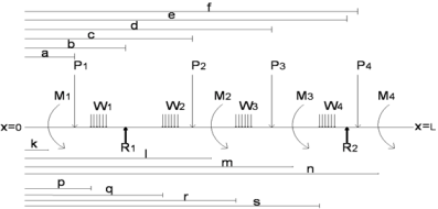
Refer to the below diagram for a simply supported beam with 4 point loads, 4 uniformly distributed loads, 4-moment loads, and supported at 2 points. Follow this diagram to use the calculation program below.
Read the guidelines before using this calculation program
1. Understand the beam diagram carefully, if any doubt please leave a comment for us to reply
2. Put the value as zero if any parameter is not applicable to your case
3. All the units are SI. Means Force in Newton and Distance in mm
4. Downward acting force is positive and upward is negative
5. Downward acting uniformly distributed load is positive and upward is
6. Clockwise moment is positive and anti-clockwise moment is negative
Example
If Force on the beam is 5000 N in a downward direction then put magnitude as 5000 in the cell
If the force on the beam is 5000 N in the upward direction then put the magnitude of force as -5000 in the cell
