What is a Coordinate Measuring Machine?
In this modern and fast-changing industrial market with Industry 4.0 coming in, Flexibility and Automation are two of the most important market requirements in Industrial Metrology. The trend of automation is closely linked to increasing throughput. This requires taking and recording the whole measurement process into consideration. Automated part loading systems, automated or guided selection of measurement programs, evaluation, and processing of measurement data all contribute to increased throughput. In addition, an inspection machine should be flexible enough to inspect and analyze various types, complex shapes, geometry, and size of parts. Additionally, manufactured part quality can be analyzed according to DIN, ISO, BS, AGMA, or ASME standards. A Coordinate Measuring Machine is one of the possible solutions to the above expectations among Metrology lab equipment.
A coordinate measuring machine (CMM) is a device that is based on the principles of 3- Dimensional Coordinate Geometry principles i.e., a Cartesian coordinate system with XYZ axes. It measures the dimensions, geometry, shape, and accuracy of the objects by sensing various points on the surface of the object with a highly sensitive probe (contact type or non-contact type) and coordinates of these points are recorded in the computer equipped with specially designed software to generate an inspection report in a pre-specified format. The probe position can be controlled by an expert CMM operator manually for simple objects or automatically by the software for complex contours, shapes, or profiles that otherwise are difficult to reach or trace such as to measure the Tooth shape of a Gear, turbine engine blades, cams, automobile bodies, crankshafts, rolling elements of a bearing or profile of a curved surface of a specific shape.
CMM’s are highly versatile, providing the ability to precisely measure different types of workpieces including small parts to heavy parts like gears, car body components of sheet metal, and bigger parts such as engine blocks or housings.
Types of CMMs to consider (based on application requirements)
Bridge CMM, Gantry CMM, Horizontal Arm and Cantilever CMM

Bridge CMM
It is the most popular type of CMM. Bridge machines have a low cost to build and the ability to maintain accuracy and repeatability over the long term. Bridge CMM comes in 2 types of Configurations- A fixed table with a Moving Bridge and a Moving table with a Fixed Bridge. Most of the Moving Bridge machines are based on a precision granite plate with two legs supporting the X-axis carriage. Generally, only one side of the bridge is driven; the other side is the slave side and is allowed to float freely. 95% of all bridge machines run on air bearings to allow friction-free movement and minimize mechanical interaction. In the Fixed Bridge type, the vertically moving arm (Z-Axis) is mounted on a carriage, the carriage (X-axis) moves horizontally on a bridge structure fixed to the base and a table (Y-axis) moves horizontally on the base. The accuracy of the Fixed Bridge configuration is higher than Moving Bridge as the servo drives are located at the center of gravity, with a moving bridge the X-axis drives along one side, so the accuracy will change as the z-spindle moves in X.
Machines are built in sizes ranging from 300×300×300 mm XYZ to 2000 mm x 5000 mm x1500mm, with some exceptions. Bridge machines are the workhorses of CMMs.

Pros & Cons of Bridge Type CMM
Pros-
The accuracy of most bridge systems is usually better than other types of coordinate measuring machines especially considering precision machined parts.
Bridge machines can be moved relatively easily within the plant either by forklift trucks or riggers and can be ready for use after calibration.
Cons-
Accessibility to the part being measured is sometimes quite difficult because of the uprights holding the X-axis beam. Heavy components have to be lifted onto the plate, necessitating a crane or a lift truck and potentially causing a collision with the machine.
Applications of Bridge Type CMM
- Machined and pressed parts
- Plastic moldings
- Casting and forgings
- Touch trigger and non-contact inspection
- Digitizing, scanning, and reverse engineering
Gantry CMM
Gantry CMM machines are used for very large or heavy parts such as structure or fabrication that require the high precision of a bridge machine. Generally, Gantry CMMs are mounted directly on the floor and therefore must have a rigid foundation as per the CMM manufacturer’s recommendation.
Smaller gantry machines have four upright columns supporting large Y-axis beams, usually 1.5 to 2 meters in height. The X-axis carriage runs along the two supported beams of the Y-axis. Whereas larger gantry machines may have six or eight columns, or even more, depending on the total length of the Y-axis. The Z-axis which is located on the X-axis carriage has a depth from 1.2 to 2 meters in general but if required depth can also be up to 4 meters also.
The measuring range of gantry CMMs can vary from 1 x 2 x 1m XYZ to 4 x 10 x 3m XYZ, and even larger for special purpose-built unit machines.

Pros & Cons of Gantry Type CMM:
- Pros:
- > Heavy parts and large components can be loaded directly & safely on the floor with the help of an overhead crane on the shop floor.
- > Machine operator or the programmer to easily walk up to the part during customization of certain features of a computer program for new parts.
- > The measurement process, while the machine is running, can be observed easily to due easy access to the part.
- > Surface plates for smaller components are easily inserted into the gantry, making measurement simpler and less tedious for the CMM operator.
Cons:- > The significant cost of building a foundation
- > Complete lack of any kind of portability. Gantry machines can be moved but need significant disassembly of pillars and reassembly after setting up the foundation at a new location.
- > Gantry CMMs take up a large amount of shop floor area
Applications of Gantry CMM
- Household appliances and white goods inspection
- Die and Mould Applications
- Flush and Gap Inspection
- Assembly Plant Setup
- Telescope optics
- Aircraft Component Inspection
Horizontal Arm CMM
The horizontal arm coordinate measuring machine consists of a vertical column (X-axis) and a horizontal arm (Z) mounted on a saddle that runs vertically up and down the X-axis. The Y-axis is then the length of a surface plate or a long beam.
There are 2 basic types of horizontal arm CMMs: Plate Mounted and Two Runways Mounted
Plate mounted
In plate-mounted Horizontal Arm CMM, the column (X-axis) is mounted on a large surface plate, usually made of steel. These machines have 2 types of configurations – Top-mounted and Side-mounted. Top-mounted CMMs are quite inexpensive in general and less accurate than side-mounted systems. Also, in the case of the Top-mounted configuration, most of the surface is taken up by guideways for the vertical column so the surface plate cannot be utilized for putting the component on it for inspection. However, the Side Mounted system allows the whole surface area of the plate to be utilized for measurement as the guideways are located on the side face of the surface plate. Additionally, It also provides a far more stable and accurate platform for measurement, as the tipping moment due to self-weight is minimized because the two sides of the plate are utilized as guideways.
Two Runways Mounted
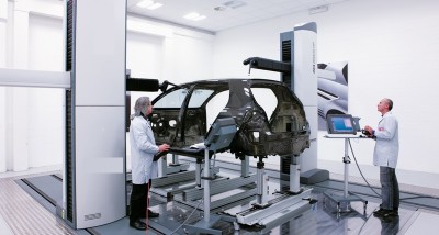
This type of CMM runs on a dedicated runway; there is no integral surface plate. This top-mounted configuration provides flexibility as it can be used singularly or as a dual-arm machine for measuring large components such as automotive bodies or sheet metal parts. The dual-arm machines allow measurement of both sides of the component simultaneously thus saving a lot of time for measurement
Measuring sizes of horizontal arm machines vary from 2 x 2 x 1m XYZ to 4 x 10 x 3m XYZ.

Pros and Cons of Horizontal Arm CMM-
Pros-
> They can measure large thin-walled/sheet-metal type components mounted in fixtures that represent car body position, such as doors, body sides, grills, dashboards, etc.
> For measuring large components that require open tolerances these types of CMMs are by far the most cost-effective solution.
Cons
Accuracy is not the strong point of the horizontal arm CMM as most of the machines perform to volumetric tolerances of 30 µm and larger
Applications of Horizontal ARM CMM
Automotive full body and panels inspection
Inspection of large parts such as mold tools, housings, castings, etc.
Integrated in-line inspection
Digitizing, scanning, and reverse engineering
Shop floor CMM or Cantilever CMM
Generally used for measuring relatively small parts, they provide open access to the operator on three sides. The X-axis measuring beam is attached on the side of a rigid structure housing the Y-axis. This limits the size of the X beam, because of inherent rigidity, making the machine suitable only for smaller components. As a shop floor CMM, the cantilever machine excels, because it lends itself well to automatic loading and unloading.
Advantages of CMM
In addition to replacing dedicated inspection equipment, CMMs can also replace many of the smaller, hand-held, and functional gages used in parts inspection.
Inspection gauges generally have issues around the lack of repeatability between operators using manual inspection methods, as well as issues concerning the slower speed of measurement in general. Such an issue does not exist with CMM.
The observations and reading with manual gages must be written down, making them subject to human error and incorrect values being recorded. An automated CMM can also measure parts while an inspector continues to perform other duties, leading to more accurate, consistent, and repeatable results and reporting. Moreover, results can be generated in a pre-specified format.
CMMs can even be placed on the shop floor alongside production machines, if rapid and dramatic temperature changes, as well as vibrations, are taken into account. If the temperature is somewhat stable, there usually will be no major noticeable errors, even given the tolerances required for components. Moreover, many modern CMMs today come with temperature sensors to help ensure proper compensation is made for any temperature fluctuations that do occur.
Software: An important part of CMM
Along with the precision and accuracy of the CMM, the specialized measurement software is key when inspecting many different types of components with precision. Optimal software modules can analyze measurement results to document, present results, and archive the data in practical structures in graphical representation or tabular form. For instance, the calculation of whether a complex shape of the manufactured component is correct based on data points extracted during measurement requires the use of high-level mathematical formulas and sophisticated algorithms.
It’s also vital to look for CMMs with software that can handle these complex calculations and can even combine intuitive icon-based programming with the ability to import native CAD models directly from the designing software. So that the entire product development cycle from Design to Prototype building can be linked.
Modern CMMs come with software having measurement programs that can be automatically loaded from a database, either by manually selecting a certain part by ID number or picture or icon by integrating devices to automatically read part information e.g. from a data matrix code. This requires a minimum of experience in components manufacturing and metrology.
Another advanced level of user interaction can be seen in the setup of the measurement programs where users can even dig deeper into the creation of the measurement program and setting up evaluation routines. So, interfaces, Tolerances, and Geometrical Parameters can be defined, and measurement procedures can be set to very individual or specific requirements based on the type of components to be inspected.
Types of CMM Probes: Contact Probes and Non-contact Probes
Probes are the most important parts of a CMM that are used during the measurement of a component, there are two basic types of probes used. The Contact Probe – physically touches the item being measured. The non-contact probe – uses lasers or machine vision. The contact probe is the most accurate of the two solutions, but non-contact probes are far quicker while still delivering extremely high accuracy levels for components such as sheet metal car body parts.
Multi-sensor probes are a combination of Contact and Laser type probes. Such probes give the user more flexibility and mean the CMM can be used for a wider range of applications with considerable time-saving.
Contact Type Probes:
These probes can be further divided into 2 categories Touch Trigger and Analogue Scanning Probes.
A touch-trigger probe has a stylus that is attached to a bearing plate. This is then connected to pressure sensors (having piezoelectric material) inside the housing of the probe. Each time the probe makes contact with the workpiece, it generates an electrical signal due to contact pressure. The signal is sent back to the CMM software to record the measurements. With a touch trigger probe, the head is mounted at the end of one of the CMM’s moving axes. The probe can be rotated either manually or automatically and can accommodate a variety of attachments and stylus tips.
Touch probes are versatile and flexible and the presence of the piezo-based sensors eliminates the effect of stylus bending. And, advancement in the strain gauge technology ensures that the probes trigger with constant force regardless of the angle of contact it has with the workpiece. These two things combined eliminate directional sensitivity which has given these probes a sub-micron level of accuracy.

Analog Scanning Probes
Analog scanning probes are another type of stylus-based probe that are used for measuring contoured surfaces such as sheet metal assemblies. Unlike digital probes, which touch individual points, the analog probe keeps continual contact with the workpiece taking measurements as it is dragged across it.
The continual contact which yields analog measurements offers dramatically increased levels of data acquisition. The structure of the continuous analog scanning (CAS) probes is based on continuous data acquisition rather than the point-to-point of a digital probe.
Analog scanning probes are extremely useful for collecting measurement data for complex contoured shapes such as turbine engine blades, cams, automobile bodies, crankshafts, and prosthetics.
There are two types of continuous analog scanning, CAS, systems:
1. Closed-Loop Systems: This probe automatically detects changes in the surface and direction of the workpiece and adjusts itself accordingly to ensure that it maintains contact at all times. The closed-loop system is particularly useful for digitizing unknown and complex shapes.
2. Open-Loop Systems: This probe gets driven along a specific path using dimensional information obtained from a data file. The open-loop system is particularly useful for high-speed data gathering on parts with geometry that has been well-defined by surface points and vectors or by CAD data.
Non-Contact Probes
A non-contact probe is essential for any workpiece that is likely to become deformed under the pressure of a contact probe. They are also useful for more complex, smaller, and high-precision workpieces. A non-contact probe is either laser-based or vision-based.
Laser Probes
A laser probe works in a similar way to a touch-trigger probe. Instead of using a stylus, it uses a concentrated beam of light to take readings. The beam of light acts as an optical switch. When the beam is projected onto the part, the position will then be read by triangulation through a lens inside the probe receptor.
This technique is similar to the one used by surveyors when they want to find a position or location with bearings from a known distance between two fixed points.
Vision-Based Probes
Microprocessors and other very small parts require the use of vision-based probes. Rather than measuring the parts themselves, a mould is electronically digitized that will generate accurate dimensions for future workpieces.
The key advantage of a non-contact probe is that it enables the user to collect data from a larger surface area in less time than is possible with contact probes. However, the downside is that the accuracy of the readings is not as great as the contact probes. If you want speed over accuracy, then a non-contact probe is ideal. If you have a particularly complex essential part, you would be better suited to using a contact probe.
Calibration and maintenance of CMMs
Regular calibration of CMM is required to maintain the accuracy level. When considering a calibrator for your coordinate measuring machine an ISO/IEC: 17025 certified provider should be the first choice. The international standard for coordinate measuring machine calibration is ISO: 10360-2 (2009). The standard mainly consists of two separate tests:
Length measuring performance designated as E. The test procedure defines a series of measurements of either a step gauge or a laser in the machine’s volume.
Probing performance testing is designated as R. This is conducted on a precision sphere, wherein random and systematic errors with the probe can be isolated and monitored.
Keywords: Coordinate Measuring Machine, CMM, Types of CMM, Advantages of CMM, Types of CMM Probes and Sensors, Applications of CMM, Industrial Metrology, CMM Software, CMM Calibration Standards, Contact Probes, Non-contact probes, Bridge CMM, Gantry CMM, Horizontal Arm CMM, Shop Floor or Cantilever CMM, Mitutoyo CMM, Hexagonmi CMM, Calibration of CMM, Measurement error,
I’m not that much of a internet reader to be honest but your sites
really nice, keep it up! I’ll go ahead and bookmark your website to come
back in the future.
Many thanks