Metal Forming
Metal forming is one of the 5 ways of Manufacturing Processes of metal components (Primary shaping, Joining, Material Treatment, Metal cutting, and metal forming). Metal Forming is defined by DIN 8580 as manufacturing through the three-dimensional or plastic modification of shape while retaining its mass and material cohesion. In contrast to deformation, forming is the modification of a shape with controlled and desired geometry. Forming processes are categorized as chip-less or non-material removal processes unlike metal cutting as such as turning, milling, drilling, etc.
Metal Forming is further classified into Massive Forming and Sheet Metal Forming.
Massive Forming example– Forging, Rolling, Extrusion, Drawing (with rollers), etc.
Sheet Metal Forming example– Bending and Straight Flanging (like brake bending etc.), Surface contouring of sheet (like stretch forming, etc.), Deep recessing and flanging (deep drawing, spinning, etc)
Let’s see some of the examples of sheet metal forming processes
Now as we are familiar with metal forming process basics, let us learn about the machine tool used to the sheet metal components into the desired shape i.e. the Mechanical Power Press
Mechanical power press (or simply mechanical press) is a machine based on the slider-crank mechanism that converts the rotating motion to reciprocating motion and force or energy in the reciprocating part is transferred to sheet metal. During the transfer of this energy, sheet metal undergoes plastic deformation, and the desired shape of metal is achieved. For example- Car body parts, steel utensils, the fuel tank of a motorcycle, shaving blades, metal cap of a medicine bottle, coins, case of computer CPU, clutch plates, etc. Are manufactured on a press.
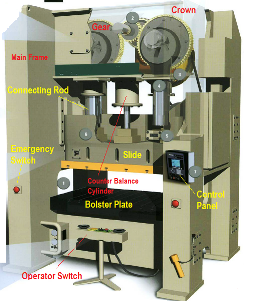
Let’s understand the basic components and terminology of mechanical power press. Refer Below 3D model view and Cross-sectional view.


Motor– It is the first most part of the press which supplies the power to the drive system. Motor power rating will depend on the capacity of the press.
Tonnage capacity– Amount of force (in tons or kilo Newtons) excreted by the reciprocating part of the press is tonnage. The tonnage of the single mechanical press can be from small 10 tons to big 3500 tons or even more. 1 ton = 10 kN, so 250 tons means 2500 kN.
Flywheel– Motor of the press is connected to a flywheel by V belts and the flywheel stores the energy which is used to perform the metal forming. The flywheel is a must in power press because a large amount of energy is spent on metal forming. The flywheel is always rotating (even if the press is not running) whenever the motor is switched on. Similar to automobile crankshaft and flywheel is rotating whenever the engine is on despite Car is moving or not.
Clutch and Brake- In modern mechanical presses Clutch and Brake are a single unit. By default, the break is active and the clutch is disengaged. After pressing the run button on the control panel, the break is disengaged and the clutch is engaged. Break is active by springs and clutch is activated by air or oil (Pneumatic or Hydraulic. Small presses have a pneumatic clutch but the large capacity press has a hydraulic clutch.
Driveshaft assembly- All the rotational motion from motor and flywheel goes to drive shaft assembly through the clutch system. Drive Pinion on the drive shaft is meshing to gear train of the press. Driveshaft assembly is the assembly of Shaft, Drive pinion, Flywheel, Clutch, and Brake.
Crown – Crown is nothing but a kind of big gear-box having the entire gear train of the press, it also supports the drives shaft assembly, flywheel, clutch, and brake.
Upright or columns or Pillars- These are the structural members which support the crown and act as a connection between Bed/ base and crown.
Slide– it is the reciprocating part and upper die it attached to it. All the tonnage force of press is applied through the slide.
Bed or Base– It is the bottom most part of the mechanical press, which supports the lower die.
Die (upper and lower)– Die is a toll, basically in 2 parts upper and lower. It has the required shape so that the sheet metal part can be made in the same shape.
Overload Protection System– Almost all of the modern mechanical presses have the Hydraulic Overload Protection System which is a closed hydraulic system and get activated whenever the force acting on the presses exceeds the tonnage capacity. A typical example can be if the operator of press inserts 2 or more layers of sheet metal (by mistake) then force transferred on a slide during forming operation will be significantly increased than designed value.
In very small presses like up to 40 Tons, Shear Plate is used instead of a hydraulic system for overload protection. This is done only to save the cost of the hydraulic system. The shear plate gets broken during overloading and is replaced again to run the machine. 
Types of Mechanical Presses
Types of Mechanical Presses –
There can be different ways of classification of the mechanical press such as type of mainframe, type of Drive Mechanisms, Number of Connecting rods or points etc
Type of Frame-
C Frame– Frame has C shape and is used for small pressed up to 250 Tons. Due to the C shape, press frame has deflection (longitudinal & Angular both) larger than other types of frame so this frame has a limitation when high accuracy is required. So, the C frame presses are more common with presses up to 100 Tons.
Single piece H Frame– All the pictures of the press cross-section view above are single piece H frame. H Frame is a rigid construction. But as it is in a single piece so for a higher tonnage capacity above 400 Tons it is difficult to handle the press inside the shop floor as the frame will become too big. So this kind of frame is preferred till 400 Tons.
Link Frame – In this, crown, pillars, bed all the separate parts and are joined by long tie rods. All big size heavy presses above 400 tons are made like this type of Frame.
Drive Mechanism– Although all the presses are based on Slider Crank Mechanism, the crank can be of 3 types- Eccentric Gear, Crank Shaft, and Eccentric Shaft. Further, instead of using simple crank dive, link drive mechanisms can be used such as Knuckle Joint and 6-link Mechanism. Link Mechanism changes the motion on slide such as making the motion slow when coming down during forming operation and going back quickly to save idle time.
Eccentric Gear- Crank portion and gear are combined. It is a robust system and is used for presses above 250 to 400 Tons and stoke above 250 millimeters.
Crank Shaft– It is used for small presses up to 250 tons commonly (sometimes up to 400 tons also). It is not robust for high stoke.
Eccentric Shaft– It is simple and robust for high speed and very low stroke machines. It is used for tonnage up to 630 Tons and a stroke of 100 to 120 millimeters or less.
Number of connecting rods– Depending on the size of press, connecting rod can be from 1 to 4 in a press.
Please see below picture for example of press with 2 connecting rods and Link drive with 4 connecting rods


Really, This Blog is very Helpful and informative. This blog are every line impressed me. You are truly well informed and very intelligent about Mechanical Power Press. If someone want to know about Mechanical Power Press then I will suggest this article will be best for all. Thank you for write a informative article.
Thank you for sharing valuable information. Really helpful and informational content. Noted so many new things from this blog. keep sharing with us. Also, Contact us for Mechanical Press Machine.
Great post. Thank you for sharing this valuable information. It is very interesting and we learned many things from this blog which helps us. Also, Contact here for Mechanical Press in Canada.