Summary
This article describes the procedure to test the sealing system applied on the Taper Bearing Unit (TBU) or Cartridge Taper Roller Bearing (CTRB) in Railway wheel application (axle box) against water ingress. The water spray test is performed to test the effective water seal and performance of the different types of sealing systems provided by various bearing manufacturers.
Background
TBU or CTBU mounted on railway axles are sealed with different types of sealing systems. Being the bearing sealing system a sensible part of the unit, the design and the accuracy of this component are relevant for the correct unit performance. To homologate the different sealing systems designed, a special mandatory test called the “water spray test” is performed according to EN12082 and/or UIC5155 Norms.
As a plus to the above mandatory tests on sealing systems with contacting rubber lip design, some bearing manufacturers perform additional tests to further guarantee a correct sealing. All the above-mentioned water spray tests are performed on a specially designed rig test (refer below pictures).
Details
Because the several sealing systems designed in addition to the different types of axle box design, in order to perform a reliable water spray test the rig test setup is configured (axlebox; rear cover, wheel, etc) as equal as possible to the real configuration present on the train and also in agreement to the Customer requirements (see below images).
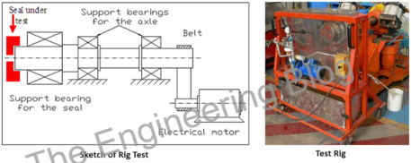
The test rig is made up of a shaft driven by a belt from an electrical motor (See sketch below). The shaft is supported by two support bearings and a third bearing as support of the sealing system to be tested.
The water spray test is performed according to the speed time cycle simulating the train step speed of the field application for the UIC5155 norm (dynamic) and in static mode for the EN12082 norm. The water spray test rig consists of spraying 3 liters/min of water, on seals under test, by a dedicated spray pipe formed into quadrants the drilled holes gave a uniform distribution of water on over top part of the seal according to EN12082 UIC5155 test condition (See graph and table below). The configured axlebox is equipped with a drainage pipe in the bottom position to measure eventual water ingress. No water ingress is admitted to pass the test. The additional test is performed according to the speed time cycle simulating the train step speed of the application to be tested (see table below).


The operative rig test speed cycles are defined in steps simulating the commercial speeds; one hour stand still and one hour at each fractioned speed until to reach the maximum commercial speed.

