What is a Railway Bogie?
Just like the chassis of your passenger car, the bogie of a Locomotive is an essential part of the train. However, a bogie has much more function to perform than a normal automobile chassis. The Bogie of a Railway Locomotive is hardly noticed by the passengers but its role is very critical it carries the locomotive’s drive system, wheel-axle, brakes, suspension system, auxiliary equipment, and guidance mechanism, and of course carry the weight of all the parts. In simple terms, a bogie is a structure underneath a railway body that carries and ties all the components of the locomotive together and axles & wheels are attached through bearings. A standard railway locomotive has two bogies (Bogie 1 and 2 in the picture), generally located near the vehicle’s ends. Each bogie is a 4-wheel set or 6-wheel set truck and the below picture is an example of 6 wheelsets of an Electric Locomotive. Bogie is also known as wheel truck, truck, or simply car, and wheelset is also known as an axle or journal.

Design Principle Elements of Bogie (Powered and Un-powered)
Railway bogies are complex subsystems in railway vehicles and contain brake systems, drive systems including gearbox coupling and traction motors for powered wheelsets, bogie frames with secondary spring systems, and the wheelset subsystems, which are basically the assembly of two wheels and an axle.
Directly connected to the wheelset and the bogie frame is the Axlebox (containing the Axlebox bearing system). The Axlebox is very much linked to further subsystems and components like primary spring systems, Axlebox guidance, dampers, steering mechanisms of wheelsets, earth return devices as well as sensors to detect operational parameters and bogie monitoring systems. Further, bogie-connected subsystems are wheel flange lubrication systems, articulation joints, slewing bearings, and special plain bearings for damper supports
All kinds of railway vehicles are equipped with running gears, which can be designed as 2- or 3-axle cars or as bogie vehicles. 2-axle car design principles are used mainly for European freight cars, shunting locomotives, and for sections of articulated cars such as low-floor light rail vehicles or tramways. Today, the majority of railway vehicles are equipped with bogies that contain mostly two axles, but in some cases, such as heavier and more powerful locomotives, 3-axle designs are used.
Powered bogie designs: The Bogie of a passenger car can be powered or non-powered. In the case of an un-powered passenger car, one or two Locomotives are used to haul the train. Here, Locomotive has the powered bogie. However, for trains such as intercity metro, subway, high-speed trains, and mass-transit vehicles the Powered Bogie multiple units are used. Typical propulsion systems in a powered bogie contain a wheelset, a gearbox, and a traction motor.
Wheelset arrangement classification
The wheel-set arrangement classification is a systematic tool to sort railway vehicles by the position of the wheel sets (axles), bogies, and connections of vehicle bodies. Although different countries may use different classifications of locomotives however the International Union of Railways (UIC) classification scheme is widely used and is written in the UIC’s “Leaflet 650 – Standard designation of axle arrangement on locomotives and multiple-unit sets”.
B’ B’ – two bogies or wheel assemblies under the unit. Each bogie has two powered axles, connected by driving rods or gears.
Bo´Bo´- two bogies under the unit and each bogie has 2 individually driven powered axles or wheelsets (power via traction motors). 75% of all modern locomotives are configured as Bo´Bo´.
Co´Co´- two bogies under the unit and each bogie has 3 individually driven, powered axles (power via traction motors).
Bo´Bo´ + 2´2´ + 2´2´- multiple units, first unit: two bogies, each bogie has two individually-driven powered axles; second and third unit: two bogies, each bogie with two non-powered axles.
Bo´ 2´ Bo´- articulated vehicle: The first and last bogie has two individually driven powered axles/middle bogie (Jacobs design) with two non-powered axles.

Now we have studied about basic details and wheelset arrangement in a bogie, let’s study about various components of the bogie. The below 3D model shows one of the types of Bo Bo bogies of a Locomotive (Powered Bogie). The reader should be aware that there are so many different designs, we can not study all in a single post.

Bogie Frame
It is the main structure made of steel plate or cast steel. Nowadays, it is made by a welded steel box format where the structure is formed into hollow sections of the required shape.
Disk Brake and Brake Cylinder
An air brake cylinder is provided for each wheel and this cylinder can operate disc brakes. Depending on design parameters and operating conditions some bogies may have two brake cylinders per wheel for heavy-duty braking requirements. Each wheel is provided with a brake disc on each side and a brake pad actuated by the brake cylinder. A pair of pads are hung from the bogie frame and activated by links attached to the piston in the brake cylinder. When air is admitted into the brake cylinder, the internal piston moves these links and causes the brake pads to press against the discs.
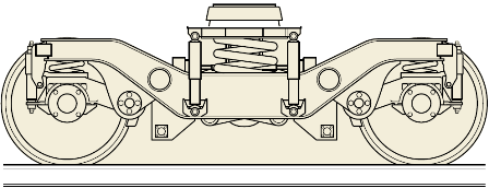
Primary Suspension Coil
The primary springs connect the Axlebox to the bogie frame. For higher speeds, a secondary spring system connects the bogie frame to the vehicle body. The springs can be designed as steel leaf or coil springs, as rubber springs, or as air springs. The aim of bogie springs is to reduce the forces and vibrations, to avoid derailment, and to uncouple vibration and noise between the wheelsets and the vehicle body. The primary spring acts between the wheelset via the Axlebox bearing and the bogie frame. The secondary spring is situated between the bogie frame and the vehicle body. Primary springs acting on the Axlebox react to vertical jounce and loads that arise longitudinally and laterally from the influence of the rail track on the vehicle body. In addition, springs decouple structure-borne noise. Enhanced bogie designs are based on different spring systems acting in several directions and using materials such as steel and rubber.
Damper (Hydraulic)
In addition to the self-damping effect of some of the spring designs, additional dampers are used. These dampers are mainly designed as hydraulic dampers acting on the Axlebox in different directions. One of the damper’s design examples is the twin-tube hydraulic damper. This device holds the wheelset on the bogie and the bogie on the rail. On both ends, either rubber elements or plain bearings are fitted. One end is typically connected with the Axlebox.
Secondary Springs
Secondary spring systems of enhanced bogie designs are a combination of air spring bellows and the rubber-metal bearer spring, which supports the system, especially when there is torsional strain and large horizontal excursions. The system also absorbs a portion of the vertical deflection and acts as an emergency spring. An additional feature of air springs is the constant leveling function that maintains the vehicle body at a consistent height, regardless of whether it is full of passengers or empty. The air is supplied from the train’s compressed air system.

Motor Suspension Tube
Depending on the design of the locomotive, it can have a motor fully suspended or mounted to the frame or may be mounted to a motor suspension tube (or simply suspension tube). If the motor is mounted (through bolts) on a suspension tube on one side and hinged to the frame on the other side. This motor is called “nose suspended”. Like the BO-BO bogie (refer to the below picture) in which the motor is fully suspended to the frame so there is no need for a suspension tube.
Gearbox
This contains the pinion and gearwheel which connects the drive from the traction motor to the axle.
Traction Motor
In General, each axle has its own traction motor. It drives the axle through the gearbox. Some designs, particularly on tramcars, use a motor to drive two axles also.

Axlebox
Axle boxes are the linking design element between the rotating wheelset and the quasi-static frame of the bogie or running gear of a railway vehicle. All forces acting between these components are transmitted via springs, dampers, and guiding elements.
Wheel Slide (or wheel slip) Protection System Lead to Axlebox
Where a Wheel Slide Protection (WSP) system is fitted, axle boxes are fitted with speed sensors. These are connected by means of a cable attached to the WSP box cover on the axle end.
Earth Return Device
The problem of electric current passing through rolling bearings like Axlebox bearings and causing damage in the contact area of rollers and inner/outer ring raceways is well-known. In addition, the electric current also damages lubricant (general grease in Axlebox Bearings). All Axlebox bearings potentially suffer from this phenomenon. Craters are formed and are known as electric pitting. In a more progressed stage, fluting or washboard patterns of multiple grey lines across the raceways of the bearings can be detected.
Earth return devices transmit electrical current from the stationary part to the rotating axle of the wheelset. These devices avoid dangerous voltages between the vehicle and the ground as well as avoid damage to Axlebox bearings by avoiding the passage of the electric current through raceways of bearing rings and rollers. The earth return acts as a low ohmic bridge that transmits the current with coal brushes to a rotating part. The maximum current is in the range of
1000 A, depending on the earth return design. In the German standard, DIN VDE 0123, electrical current flows in railway vehicles are explained in detail, and suggestions to avoid current passing through Axlebox bearings are proposed.
Keywords: Bo Bo Bogie, Co Co Bogie, Bogie of a Railway Locomotive, Bogie of a Railway coach, design of railway bogie, gearbox, primary suspension, secondary suspension of locomotive, railway wheel slip protection, suspension tube, traction motor