Cranes for Material Handling and Construction Industry
A crane is a Tower or structure provided with a system of hoists or wire ropes, chains, and pulleys that is used to pick up and place the heavy load and move them at the required location. Any crane uses one or more simple mechanisms to create a mechanical advantage to move heavy loads. Cranes can be stationary such as at a building construction site or mobile such as the crane used to carry accidental vehicles on the highways. Construction cranes are usually temporary structures, either fixed to the ground or mounted on a purpose-built vehicle.
Cranes may either be controlled by an operator in a cab that travels with the crane, or by radio control. Where a cab operator is involved at a height or distant location from the material to be picked the workers on the ground will communicate with the operator through a system of standardized hand signals or, in larger installations, a radio communication system.
There are three primary considerations in the design principles of cranes: the crane must be able to lift the weight of the load, the crane must not topple and third, the crane structure must not collapse.
Articulation Joint of Pick and Carry Crane
Along with lifting the material in the vertical plane, Pick and carry cranes need to move the material in the horizontal direction also. For this, the front body (consists of hoist winch, motor, gearbox, ropes & brakes) and rear body (generally driver operating cabin) of the crane are connected by the articulation joint and hydraulic cylinders for turning about the vertical axis. Loads at articulation joints are supported by the Spherical Plain Bearings. Also, the hydraulic cylinder rod ends are supported by spherical plain bearings.


Loads calculation on Articulation joint & Spherical Plain Bearing Selection
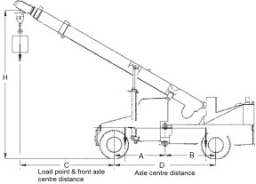
Articulation joint bearings are subjected to moment loads due to the load suspended on the hook of the extendable boom. Moment load should be converted to radial and axial loads assuming an overhand beam with the center distance between all the supports & loading points.
Application data (example of 35 Tons pick & carry crane)
- Machine: 35 Ton Pick & Carry Crane
- Moment due to load: As per the duty cycle
- Radial load: As per the duty cycle
- Axial load: 5% radial load
- Half of the Oscillating Angle β: 40 degrees
- Frequency of oscillation f: 1 min-1
- Time to complete oscillation t: 60 seconds
- Ambient Temp: 50˚ Celsius
- Max Load to carry: 35 Ton
- Distance from load point to front axle: 1.5 m
- Load is acting in constant direction:
- Duty Cycle: As per the below table
Duty Cycle (for 35 T capacity Pick & Carry Crane)
| Duty % | Load (Tons) | Distance (meter) |
|---|---|---|
| 5% | 35 | 1.5 |
| 5% | 26 | 2 |
| 60% | 13 | 3.5 |
| 20% | 24 | 2 |
| 10% | 2 | 16.5 |
What is a Spherical Plain Bearing
Spherical Plain Bearings are an excellent choice when shaft misalignment is high, especially for oscillating, tilting, or slow-rotating machinery with High static load. Their design makes them unaffected by deflections or misalignment compared to rolling element bearings. There are various options available from manufacturers such as Steel on Steel and Steel on Bronze. there are even maintenance-free solutions that have sliding material with PTFE fabric, PTFE composite, or sinter bronze that do not even needs lubrication. Unlike rolling bearings, plain bearings have load distributed over a large contact surface, giving low specific load and good sliding properties. But sliding velocity becomes very high, which gives high operating temp. So they are suitable for high-load and low-speed applications.
The selection process of spherical plain bearing for Articulation Joint
For selecting the suitable size of spherical plain bearing we need to identify the Radial and axial load. We are considering SKF Spherical Plain Bearing GEH 110 ESX-2LS as an example for this case. The L10 life of the bearing is calculated from online calculation software available on SKF Website.
Method 1: The moment at the front wheel is directly transferred to the articulation joint (conservative approach)
Method 2: The moment is calculated at the articulation joint with overhang beam theory (more realistic to practical conditions)

L10 for Articulation Joint Bearings- GEH 110 ESX-2LS (Considering the moment at articulation joint)
| Duty | Load (T) | Distance (m) | Moment at Articulation Joint (Tm) | Centre Distance Between Plain Bearings | Radial Load (T) | Radial Load kN | Axial Load kN | Ratio Axial/Radial | GEH 110 ES-2LS L10 (hours) |
|---|---|---|---|---|---|---|---|---|---|
| 5% | 35 | 1.5 | 57.75 | 0.7475 | 38.63 | 386.3 | 19.3 | 0.05 | 3430 |
| 5% | 26 | 2 | 57.2 | 0.7475 | 38.26 | 382.6 | 19.1 | 0.05 | 3550 |
| 60% | 13 | 3.5 | 50.05 | 0.7475 | 33.48 | 334.8 | 16.7 | 0.05 | 5890 |
| 20% | 24 | 2 | 52.8 | 0.7475 | 35.32 | 353.2 | 17.7 | 0.05 | 4800 |
| 10% | 2 | 16.5 | 36.3 | 0.7475 | 24.28 | 242.8 | 12.1 | 0.05 | 19800 |
| Equivalent Life in hours | 5642 |
L10 for Articulation Joint Bearings- GEH 110 ESX-2LS (Overhang beam method)
| Duty | Load (T) | Distance (m) | Moment at Articulation Joint (Tm) | Centre Distance Between Plain Bearings | Radial Load (T) | Radial Load kN | Axial Load kN | Ratio Axial/Radial | GEH 110 ESX-2LS L10 (h) |
|---|---|---|---|---|---|---|---|---|---|
| 5% | 35 | 1.5 | 28.875 | 0.7475 | 19.3 | 193.1 | 9.7 | 0.05 | 12000 |
| 5% | 26 | 2 | 28.6 | 0.7475 | 19.1 | 191.3 | 9.6 | 0.05 | 12400 |
| 60% | 13 | 3.5 | 25.025 | 0.7475 | 16.7 | 167.4 | 8.4 | 0.05 | 20400 |
| 20% | 24 | 2 | 26.4 | 0.7475 | 17.7 | 176.6 | 8.8 | 0.05 | 16800 |
| 10% | 2 | 16.5 | 18.15 | 0.7475 | 12.1 | 121.4 | 6.1 | 0.05 | 50400 |
| Equivalent Life in hours | 19,418 |
1