Cylinders (Hydraulic and Pneumatic)
Cylinders become their most important component by converting fluid pressure and flow to force and velocity. Like a crankshaft converts the reciprocating motion of a piston into a rotating motion, the hydraulic or Pneumatic cylinder converts the converting the fluid energy into linear motion (in the form of mechanical energy). So being one of the most basic of fluid power components, cylinders have evolved into an almost endless array of configurations, sizes, and special designs.
Lifting, lowering, locking, and moving of loads are the main applications of cylinders.


Single Acting Cylinder
A single-acting cylinder can exert force only in one direction as they accept pressurized fluid on only one side of the piston; volume on the other side of the piston is vented to the atmosphere or returns to the tank. The piston can be returned to the original position by spring, the weight of the piston, or by external force on the system. Imagine a hydraulic jack for vehicles that represents a common application of a single-acting, gravity-return cylinder.
Single-acting cylinders depending on whether it is routed to the cap end or rod end, the pressurized fluid may extend or retract the cylinder, respectively. In either case, the force generated by gravity or a spring returns the piston rod to its original state.
Single Acting Cylinder (spring return type) –
Single-acting cylinders can be spring-extend or the more common spring-return type. Some examples are –
1. A spring-extend cylinder is useful for tool-holding fixtures because spring force can hold a workpiece indefinitely.
2. The cylinder then releases the workpiece upon application of hydraulic pressure. Spring-applied/hydraulic-pressure-released (parking) brakes represent another common application of single-acting, spring-extend cylinders.
3. Factory automation—especially material handling—is a common application using pneumatic spring-return cylinders.

Single Acting Cylinder (plunger type) –
Plunger cylinders are used when a definite direction of the external force will definitely return the piston to its starting position. These cylinders can be designed with or without stroke limiters. Some examples are- upstroke presses, cutter stroke tables and lifting devices.

Double Acting
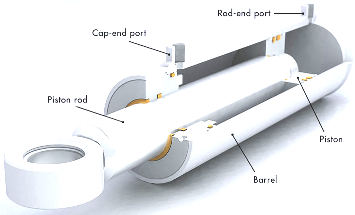
Double-acting cylinders have two opposing effective areas that are of same or different sizes. They are fitted with two pipe ports which are separated from each other. By feeding pressurized fluid by port A or B, the piston may transfer pulling or pushing forces in both directions. Simultaneously, fluid on the opposite side of the piston flows back into the hydraulic reservoir or tank. (If air is the fluid medium, it usually is vented to the atmosphere.)
Because the area of the rod-end piston face is smaller than the cap-end area, the extension force is greater than the retraction force (assuming equal fluid pressures on both sides). Because total cylinder volume is less with the piston rod fully retracted (because of rod volume) than when it is fully extended, a cylinder retracts faster than it extends (assuming equal flow rates on both sides).
The double-acting cylinder can have a single-piston rod or a double-piston rod. In the case of a double-piston rod, the area on both sides of the piston can be the same or different. Refer to below pictures.


Tandem Cylinder–
In double-acting cylinders operating in tandem, there are two cylinders which are connected together in such a way that the piston rod of one cylinder, pushes through the bottom of the other cylinder to its piston area. By using this arrangement the areas are added together and large forces may be transferred for relatively small diameters without increasing the operating pressure. However, the longer length of this model must be taken into account.

Rapid traverse cylinder (single-acting)
With this type of cylinder, as long as not the whole working force is required, only part of the effective piston area, the so-called rapid traverse piston is pressurized. The total effective piston area is connected later to the hydraulic pump, by the response of pressure valves or limit switches. The advantages are as follows: high rapid traverse speed due to the low volume of fluid and high compression force due to a large effective piston area. Rapid traverse via connection port A1; compression force via connection port A2; return travel via weight of the piston or by the external load.
Similarly, a double-acting rapid traverse cylinder can exert force in both directions. Rapid traverse via connection port A1; compression force via connection port A2; retracting movement via port B.
Major applications of rapid traverse cylinders are in presses.


Telescopic Cylinder-
These cylinders are used when a long stroke is required in an application and space is limited in the retracted condition of the cylinder. For example, hydraulic lifts, tilting trailers, and lifting platforms use telescopic cylinder. These cylinders can have 2 ,3, 4 or 5 stage cylinders. If the pressure is applied via port A, cylinders will extend one after another. The piston with the largest surface area will extend first.
In telescopic single-acting, retraction happens by the external load whereas in telescopic double-acting retraction happens due to pressurized fluid supply through port B.


Standard Configurations (Tie Rod and Mill Type)
Construction variations for single- and double-acting cylinders are based primarily on how the two end caps (top & Bottom of the cylinder) are attached to the barrel (cylinder tube). Additional variations include wall thickness of the barrel and end caps and materials of construction.
Tie-rod cylinders
Tie-rod cylinders have square or rectangular end caps secured to each end of the barrel by rods that pass through holes in the corners of the end caps. Nuts threaded onto the end of each tie rod secure the end caps to the barrel. Static seals in the barrel/end-cap interface prevent leakage. A number of variations to this design exist, including the use of more than four tie rods on a cylinder, or long bolts that thread into tapped holes in one of the end caps.
Tie-rod cylinders are the most widely used design in all of the fluid power: industrial and mobile hydraulics and pneumatics. Industry standards exist for basic design, but many variations often applied to make tie-rod cylinders lighter or more compact, or provide other benefits.
The majority of cylinders for industrial, heavy-duty applications use tie-rod construction and usually conform to the National Fluid Power Association (NFPA) standards. These standards establish dimensional uniformity so cylinders from multiple manufacturers can be interchanged. However, care should be taken when interchanging cylinders because even though it conforms to NFPA dimensional standards, a cylinder may have proprietary features from its specific manufacturer that may not be available from a different manufacturer.
Welded cylinders
Welded cylinders have end flanges welded to the barrel and an end cap attached to each flange. End caps are secured in place by bolts that slip through holes in each end cap and thread into tapped holes in each end flange. This construction is lighter and more compact than the standard tie-rod configuration, which explains why welded cylinders find wide applications in mobile equipment.
A variation to this construction has each end cap threaded into the end of the barrel. This construction, however, usually cannot accommodate as high a pressure rating as welded and can be more difficult to disassemble and reassemble.
Mill-duty cylinders
Mill-duty cylinders have flanges welded to the ends of the cylinder barrels with end caps of the same diameter as the flanges. Bolts secure the end caps to the flanges. Their construction is similar to that of welded cylinders, but mill-duty cylinders have thicker barrel walls and heavier construction in general.
Mill-duty cylinders have flanges welded to both ends of their barrel with an end cap bolted to each flange.
Large mill-duty cylinders often have a barrel wall thick enough for the end cap bolts to be threaded directly into the barrel wall. As the name implies, these cylinders were originally designed for use in steel mills, foundries, and other severe-duty applications like shipbuilding, cranes, civil engineering, offshore applications, etc.