Drive System of a Railway Locomotive
All modern Electric & Diesel locomotives are hauled by traction motors. An electric locomotive is powered by electricity from overhead high-tension (voltage) electric lines through pantographs and transformers. In contrast, a diesel locomotive has a Traction Alternator connected to the engine & electricity generated by the alternator is used to power traction motors. Nowadays, Alternating Current (AC) traction motors are more common compared to DC Tractor motors due to various advantages (better efficiency, lower maintenance, etc.)
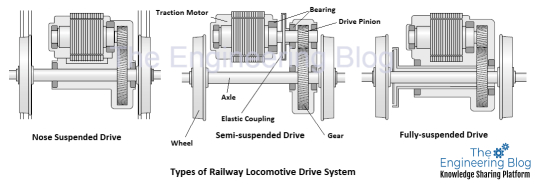
In medium-speed railway applications (such as freight or goods locomotives), the Traction motors are connected to the wheel-axle through a gearbox (single-stage or multi-stage reduction), and the whole assembly of the traction motor is mounted on a Suspension Tube, also known as MSU (motor suspension unit). Most of the MSUs are nose suspended, which means that the traction motor is supported partly via the bogie frame while the other part is directly connected via the gearbox to the wheelset (as shown in the picture). However, High-speed trains (passenger train locomotives) don’t have MSU because of the limited dynamic behavior (traction motors with MSU assembly have high suspended mass). In such cases, the Traction motor is fully suspended/ mounted to the bogie. The traction motor transfers the torque through a gearbox and/or flexible coupling.

In this topic, we will discuss bearing load calculations for both tractor motors (for a Nose-suspended drive). The selection of these bearings is one of the most critical steps in designing the drive system of a railway locomotive.
Loads (due to power transmission) calculation on Traction Motor bearings
Traction motor bearings are subject to forces due to power transmission through the gear train and External forces that arise from the inherent weight of the shaft and the other components that it carries, and the other inertia forces are either known or can be calculated. Also, there are additional dynamic forces like shock loads because of unbalance, and irregularities from tracks. It is often necessary to rely on estimates based on experience with similar machines or bearing arrangements under load. For the calculation of loads from power transmission, the shaft is considered as an overhang simply supported beam resting on rigid, moment-free supports for the sake of simplification.
Loads on bearings are evaluated as per the Torque vs RPM curve of the traction motor for the duty cycle of the locomotive at various speeds. Below is one of the examples for the same. Duty cycle means at what % of the time the train will run at a particular speed.


Online Calculator for Traction Motor Bearing Loads–
Use this online calculator for Traction Motor Gear load calculation: https://theengineeringblog.com/railway-traction-motor-bearing-load-calculation-online-interactive-calculator/
After the calculation of Gear loads. The load on Bearings are calcualted by assuming the traction motor shaft as an overhang beam. After this, suitable calculation software (or manual calculation) can be used to estimate the bearing L10 life, Lubricant selection, Lubricant life, etc. In this case, as the bearing loads are calculated as per the duty cycle so weighted average bearing life should be calculated.
Shocks & Vibrations in Railway Drive System Bearings-
Railway vehicles are subjected to shocks & vibration while running on the track. These Shocks and vibrations may come from track irregularities, structural vibrations of suspended mass, sudden accelerations & decelerations, track switchover, etc. Vibrations may come from all 3 directions- Longitudinal, Transverse, & vertical. So the designed equipment must be able to withstand the environmental vibrations.
ICEC 61373 (International Standard Railway applications – Rolling stock equipment – Shock and vibration tests) provides the reference values of shock and vibrations for railway equipment from actual service measurements submitted by various bodies from around the world. In addition to the loads from Weight, Gear force, moments, etc., the additional loads on the Bearing must be evaluated as per these reference values.
Finite Element Analysis of Cage of Traction Motor Bearings
The cage is the weakest element of a Bearing, as the Traction motor is often subjected to shocks & vibrations during operation. The bearings mounted inside the traction motor also experience the same level of vibrations, which mostly affects the cages used inside the bearings. Hence, the verification (Finite element analysis) of these bearing cages is very important against the vibration or acceleration levels.

End of topic.
Keywords: Traction Motor, Suspension Tube, Design calculations of Traction Motor Bearings, Design Calculations of Suspension Tube Bearings, Types of Motor Railway Locomotive Drive Systems, Fully Suspended Traction Motors, Nose Suspended Traction Motors, Partially Suspended Traction Motors, Drive System of High-speed railway locomotive, Drive System of medium speed railway locomotive