What is a Constant Velocity (CV) Joint?
Vehicles of all types are comprised of small components that, might not get too much attention but plays a significant role in safe driving and operational performance. One of the most important parts of the vehicle is the Driveline System where the CV or the Constant Velocity Joint can be found.
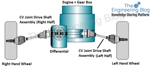
Ever imagined how a modern car takes smooth turns or negotiates any road bump without any feeling of loss of torque from the engine /differential. Actually, All modern cars with Front-wheel drive and all-wheel drive with independent suspension have a special drive shaft that connects the differential and wheel through Contact Velocity Joint. This CV joint helps the driveshaft to transmit the torque at an angle when a car takes turns or a sudden bump comes on the road. They provide the same output velocity in relation to the input velocity that is independent of the angle at which the input and output shafts operate. This contrasts with most other joints such as Universal Joint, which may provide a different output velocity at sharper angles even with the same input velocity. In this way, these side drive shafts help in transmitting torque through an angle maintaining the same rotation speed, and hence, ensuring a smooth ride of the vehicle. Most of the modern CV joints are based on Alfred Rzeppa’s 6 Ball Design CV joint invented in 1927.

Brief History of CV Joint
1550 Geronimo Cardano – Gimbal suspension. Cardan joint
1663 Robert Hooke – Cardan joint developed.
1904 Clarence Spicer- Series production driveshafts. USA
1914 Edward Hardy – Flexible coupling. the UK
1927 Alfred Rzeppa. – 6 ball CVJ
1931 DKW F1 Front-wheel driven car produced
1934 Bernard Stuber, Improved cage control
World War years – Jeeps- military, 4-wheel drives. Tracta joint etc
1946 Bill Cull – Elliptical track form -AC Angular contact.
1958 Alec Issigonis – CVJ front-wheel driven Mini- Car
1960 Michel Orain – Tripod joints, Fixed and plunging.
1962 Lobro VL joint developed.
1965 Gaston Devos + Birfield – Double offset plunging joint.
1972 Mass production of UF fixed joint
1989 Mass production of AAR plunging joint
1990s Global Standardisation of CV joint design
2000s Continues improvements in CV joint design
Components of Drive Shaft and CV Joint Assembly
Below picture is the exploded isometric view of the CV joint assembly.

Outer Race: Outer Race side is an angular joint. Angular movement of the shaft takes place here during the steering movement of the wheel. Assembly of the cage, inner race & balls along with the outer race helps in angular movement. The outer race has the male splines on one side where it gets connected to the female spline of the car wheel.
Cage: The cage holds all the components like the inner race and ball together. The cage has six pockets (in general) which hold all the balls along with the inner race. The cage is the weakest element in the entire assembly being made of thin cross-section material. Generally, in case of heavy shock load on the drive shaft cage is also susceptible to Shear Failure.
Inner Race: Inner Race is a special shape component that has six curved profiles (in general) on which balls travel during the angular movement of the shaft. On the bore, the inner race has the female splines which are connected to the drive shaft of the male splines.
Balls: Balls connect the Inner Race and Cage together for transmitting the torque. During angular movement of the shaft, Balls move in the curvature profile on the Inner Race’s surface.
Bell Joint: The assembly of the Outer Race, Inner Race, Ball, and Cage is known as the bell joint.
Shaft: The shaft (or drive shaft) is the connecting element between various parts of the CV Joint. Such as Driveshaft between Bell Joint and Tripod Joint.
Tulip: The tulip side is a fixed joint connected to the engine differential by the splines, which allows plunging (to and fro) movement while there is an angular movement of the shaft in the Outer Race side. Tulip has 3 linear tracks on its inner side. The tripod moves on this track during the angular movement of the shaft.
Tripod: The tripod is the three-pointed yoke is the part that helps in the plunging movement inside the track linear track of Tulip. Tripod has 3 rollers (with needle roller bearings) on the pointed yokes that rotate on the cup-shaped track inside the Tulip to facilitate the plunging movement. The tripod has female splines by which it is connected to the drive shaft.
Tripod Joint: A tripod joint is the assembly of a Tulip and a Tripod. A typical Tripod joint has up to 50 mm of plunge travel and 26 degrees of angular articulation; the tripod joint does not have as much angular range as many of the other joint types but tends to be lower in cost and more efficient.
Boot Cover: The boot cover is rubber material with a ribbed-like design that protects the CV joint from all known elements that can contaminate them (dust, debris, mud, or other particles on the road). It is also used as a component that keeps grease (molybdenum disulfide) that lubricates the CV joint intact with the joint itself. With a CV boot failing, cracking, or in a bad condition, the joint then becomes vulnerable to sand, dirt, rocks, and water that can rapidly wear joint components resulting in an entire replacement of the axle shaft assembly. So these boot covers are made of wear-resistant special rubbers such as neoprene that can withstand harsh environmental conditions such as vibrations, temperature variation, stress due to movement of components inside, and others
Accessories: There are some other components on CV joints like Circlips, Clamps, bolts, etc. to keep the components like boot cover, etc. in place.
Comparison in Angular Velocity of Single Hooke’s Joint & Constant Velocity Joint
The below graph shows the linear performance of CVJ as compared to the fluctuating behavior of Hooke’s joint. Here, the angular velocity varies with the joint angle for a Hooke’s Joint whereas the CV joint transmits the power at contact angular velocity at various angles. This characteristic of the CV joint makes it suitable for use in cars for a comfortable and smooth ride while the car takes a turn. There is no denying the fact the other parts of the vehicle like the Suspension system, steering mechanism, and differential type also play a role in smooth ride quality but the importance of the CV joint can not be ignored. It is the CV joint only that makes the rotation of the wheel drive shaft rotate at the same angular velocity at various angles during a turn or road bump. Considering the below graph, Now imagine the feeling of driving a car that is equipped with a normal joint between the differential and wheel!

End of Topic
Keywords: AAR Plunging Joint, Alfred Rzeppa CV Joint, Angular Velocity, Balls, Bell Joint, Boot Cover, Cage, Cardon Joint, Constant Velocity Joint, CV Joint, differential, Drive Shaft, Driveline System, Four Wheel Drive, Front Wheel Drive, Hooke’s Joint, Inner Race, needle roller bearing, Outer Race, Rear Wheel Drive, Rollers, Torque, Tripod Joint, Tulip, UF Fixed Joint, Universal Joint
Thanks for an idea, you sparked at thought from a angle I hadnt given thoguht to yet. Now lets see if I can do something productive with it.
Do you care if I reference some of this on my page if I include a link to this site?
OK from my side.
This is a appealing article by the way. I am going to go ahead and bookmark this post for my sister to read later on tonight. Keep up the good work.
I have been browsing online greater than 3 hours today, yet
I by no means found any fascinating article like yours.
It is lovely price enough for me. Personally,
if all website owners and bloggers made just
right content material as you probably did, the internet will
be a lot more helpful than ever before.
After read a few of the blogposts on your web site now, and I really like your style of blogging. I bookmarked it to my favorites site list and will be checking back soon. Pls check out my internet site as well and let me know what you think. http://www.xmc.pl