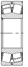
Spherical Roller bearings (SRB) are the most widely used bearings from the specific application point of view, such as Fans, Crushers, vibrating screens, Motors, Generators, or Gearboxes, Conveyors, Flywheel, Mechanical press, Drive shaft clutch, carriage wheels, etc. (list may be longer). Interestingly, the old design of the Railway Carriage also had a spherical roller bearing on the axle. Some of such designs may still be in use in certain parts of the world ( though now changed to Taper Bearing Units). They come in as big as 500-800 mm diameter (even bigger than that). SRBs can take Radial as well as Axial Loads. There are special spherical roller bearings for specific applications such as vibrating screens, so that the weak parts of the bearing, like the cage, etc, do not break during operation.
Mounting of the bearing is extremely crucial because a wrongly mounted bearing may not perform to the designed life. With wrong practice, there may be premature failure due to initial damage to the new bearing, which may not be visible. It is not wrong to say that around 1/4th of bearings fail due to wrong mounting practice.
Similarly, the removal or dismounting of the bearing is also crucial to avoid any damage to the shaft or other components, including the bearing itself, if it is to be reused.
Mounting Process Categories:
Broadly, we can categorize the bearing mounting process into the following 3 types.
- Mounting on a tapered shaft surface (or Tapered Bore Bearing on Tapered shaft)
- Mounting on a Cylindrical shaft (or a straight bore bearing on a straight shaft)
- Mounting with adapter sleeves or Withdrawal (or straight shaft and Taper Bore Bearing)
Mounting on tapered shaft surface (or Tapered Bore Bearing on Tapered shaft)
This method is primarily used for large bearings (d > 200 mm). The bearings are normally mounted and dismounted by the oil injection method (we will see this method later). This is a definite advantage compared with mounting directly on cylindrical journal seatings, when large bearings are used. Such as, Tapered journals may be used when very heavy interference fits are required. We can easily control the specific residual radial internal clearance. Not only this, Tapered journals are favorable for preventive and breakdown maintenance activities, also when mounting/dismounting is to be repeated on several occasions. From the machine design point of view, Tapered journals can carry heavier radial loads than cylindrical journals for the same bearing size (d) owing to the larger diameter of the inner end of the journal.

Mounting on a Cylindrical shaft (or a straight bore bearing on a straight shaft)
It is a simple mounting method for small and medium-sized bearings (d ≤ 200 mm) with commercially available tools, for example, induction heaters & pullers. Small bearings (d ≤ 100 mm) are normally dismounted with pullers. In the case of larger bearings, the oil injection method is normally used along with a puller. This method is preferred for mounting large bearings (d > 200 mm) when there is no likelihood of frequent mounting/dismounting for maintenance purposes (or bearings have longer L10 life). Direct mounting is used for bearings where a clearance fit on the journal (shaft) seatings is required. In some applications, conditions such as the Rotating outer ring load (e.g., vibrating screens) or low speed (e.g., crane wheels) require such a clearance fit.

Mounting with adapter sleeves or Withdrawal (or straight shaft and Taper Bore Bearing)
The biggest advantage of adapter sleeve mounting is that the commercial drawn shafts can be used. It is very simple to mount as small bearings (d ≤ 100 mm) may be mounted using a hook or impact spanners, while larger bearings require hydraulic tools. From a design (and maintenance at a later stage) point of view, Adapter sleeves require space behind the bearings for the use of pullers when dismounting. Adapter sleeves are normally used only for small and medium-sized bearings (d ≤ 200 mm). In general, there is no need for shaft abutments when mounting and if bearings operate under no or light axial load.
Adapter sleeves are used when the bearing inner and outer rings are both required to have interference fits. In fact, Adapter sleeves may be preferred when a very heavy interference fit is required. When there is a need to achieve a specific radial internal clearance adapter sleeve may be helpful.
Withdrawal sleeves offer the same properties as adapter sleeves, apart from the actual mounting and dismounting operations. On account of the simpler dismounting procedure with withdrawal sleeves, these sleeves are used for bearings that are slightly larger than those for which adapter sleeves are employed. These do not require space behind the bearing for the dismounting operation. One limitation is that Withdrawal sleeves require a shaft abutment. Small bearings (d ≤ 80 mm) may be mounted with hook or impact spanners. Larger bearings require hydraulic tools. Withdrawal sleeves differ from adapter sleeves with respect to having two sliding surfaces.
This is important to note that Sleeves (adapter or withdrawal) may add additional radial runout to the inherent runouts of the shaft and bearing. As a thumb rule, the radial runout of a bearing mounted on a sleeve may be around three times that of a bearing mounted directly on the shaft.
The bigger size adapter sleeves as well as with also come with holes for facilitating oil injection.

Oil Injection Method
The oil injection method is widely used for mounting and dismounting components with an interference fit in practically all branches of mechanical engineering and is not limited to rolling bearings.
The method involves the injection through ducts and distribution grooves of oil under pressure, for rolling bearings up to 50 MPa, between the mating surfaces. An oil film is thus formed so that the mating surfaces are fully separated and the requisite mounting or dismounting force is considerably reduced.
The method can be used for tapered or cylindrical mating surfaces. A combination of the oil injection method with a hydraulic nut is particularly useful, especially for mounting large bearings on tapered seatings. For the oil injection method to be used, the shaft or, where applicable, the unthreaded tapered sleeve or withdrawal sleeve, must be provided with ducts and distribution grooves. If these are not present, they may be made, for example, at the time the machine is overhauled.
There can be 2 conditions during Oil Mounting.
Tapered mating surfaces and Cylindrical mating surfaces
Tapered mating surfaces
The oil injection method can be used for mounting and/or dismounting bearings with a tapered bore. The distribution groove should be positioned at a distance of approximately one-third of the bearing width from the end of the seating from which mounting takes place. When driving up the bearing on the tapered seating, it is advisable to use the method in conjunction with a hydraulic nut. It is also easy to dismount a bearing that is mounted on a tapered seating, because the bearing frees itself as soon as oil is injected between the mating surfaces. In the latter case, a stop must be provided; otherwise, the bearing could be ejected from the shaft with great force. A lock nut is suitable for this purpose.
Cylindrical mating surfaces
For bearings with cylindrical bores, the oil injection method can only be used for dismounting. For spherical roller bearings with d ≤ 400 mm, the oil distribution groove should be positioned at a distance of approximately one third of the bearing width from the end of the seating from which mounting takes place. For larger bearings, it is recommended that the journals be equipped with two ducts and two oil distribution grooves.
When the bearing has been withdrawn past the distribution groove, oil can no longer be injected between the mating surfaces. Therefore, if the oil drains away too quickly, the bearing can make metal-to-metal contact on the part of the seating not exposed. It is important to withdraw the bearing quickly and in alignment, preferably using a self-centring puller; otherwise, there is a risk that the oil, even though viscous, will leak from the mating surfaces and allow the bearing to resume its interference fit.
Mounting Bearings with a Tapered Bore
Measures to prevent inner ring skew when the inner ring is not mounted against an abutment
Generally, it is possible to mount spherical roller bearings with the aid of a lock nut and hook or impact spanner if the bearing bore diameter, d ≤ 100 mm. However, if two surfaces slide during mounting (withdrawal sleeve mounting), d ≤ 80 mm is valid. When using this mounting method, there is a risk that the inner ring will end up slightly askew if it is not mounted against an abutment. This applies in particular when the bearing is being mounted on an adapter sleeve.
When the inner ring has been driven up to its final position, the hook spanner is to be repositioned in a slot in the nut at 180° to that used for tightening, and a light hammer blow applied to the spanner will straighten up the ring on its seating.
If the bearing is mounted on the tapered journal seating, the journal normally has oil injection ducts. As part of the mounting operation, oil is then injected at the same time as the nut is tightened. To prevent inner ring skew, the ring is usually driven up a little more than required. The pressure is then released, and the residual radial internal clearance, which is somewhat too small, is measured. The correct residual clearance is then obtained by slackening off the nut enough to achieve the necessary increase in clearance. To get the ring to finally slide back against the nut, and at the same time straighten up correctly, oil is injected once more. This mounting procedure is also recommended for adapter sleeves with oil injection ducts.

Mounting with the aid of a hydraulic nut is generally a very reliable method. Even so, the inner ring may be driven up slightly askew on the tapered seating, because of varying contact pressures (friction) between the inner ring and journal seating or between the hydraulic nut and its piston. If the inner ring is not driven up against an abutment and there are exacting precision requirements, a check should be carried out before the bearing is fully driven up to ensure that the distance between a reference face on the shaft and the inner ring face is the same all the way round. If the inner ring is found to be askew, and the piston has been driven out near to its limit, the skew can be reduced by unscrewing the hydraulic nut, pressing the piston back, screwing the nut on again, and resuming the drive-up operation. By doing this, the skew risk is reduced, as the radial guidance of the piston in the nut is the maximum possible. If the precision requirement is very exacting, it may be best to use a flanged spacer.
