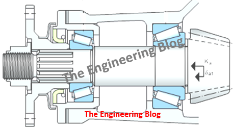
This article specifies the procedure on how to adjust a set of TRBs (Taper Roller Bearings) for a gearbox during mounting. Generally, bearing fitters do this based on practical experience, however, this topic will be a guide for new people in the bearing mounting field or application engineers to understand in general. So one should have a common understanding of the process and concept.
Taper Roller Bearings are among the most used bearings in the industry (after deep groove ball bearings). Some of the common examples of application are Industrial and automotive gearboxes, Hydraulic Pumps, Hydraulic motors, Off-highway vehicles, screw compressors, Rolling mill bearings, cranes, and material handling equipment.
In this article, we will take examples of both Face to Face (FTF) and Back to Back (BTB) arrangements.
Basics: Importance of Preload (Why Preload is required)?
Taper Roller bearings can be made to run under Clearance or Under Preload also. It depends on the requirements of the application to run the bearing on preload or clearance. An application requiring precision requires medium to heavy preload.
A (Taper Roller Bearing) TRB can accommodate radial and axial loads simultaneously. Under radial load, the force acting in the axial direction will be produced in the bearing, and this must generally be accommodated by a second bearing, which faces in the opposite direction to the first one. Purely radial displacement of one bearing ring in relation to the other will mean that half of the bearing circumference (i.e. half of the rolling elements) is under load and the axial force produced in the bearing will be Fa = 0.5 Fr/Y. Where Y can be found in the bearing manufacturer’s catalog.
Now this Fa acting on the Left side bearing may cause the separation of rollers from its raceway if Fa is higher than the axial load on this bearing. This left side bearing becomes axially unloaded which will lead to early failure. So it is must to preload the bearings to compensate for the play produced as a result of the elastic deformation of the bearing taking the axial load (Fa) into account and to achieve a more favorable load distribution.

Heavy Preload leads to :
High stiffness and load carrying capacity, optimum load distribution, and roller guidance but also increased friction and high operating temperature. If the heat generated during running of the machine is not dissipated then preload may further increase and cause seizure of the bearing. Generally, circulating oil lubrication is used in such cases which helps to maintain the temperature of the system.
Light preload or at least zero clearance under operation leads to :
Good to sufficient load distribution, acceptable friction, and temperature (if suitable bearings are used) and Reliable operation when high stiffness is not a primary target.
Mounting procedure for TRB for vertical shaft direction
We will take the example of a set of TRBs (two single bearings) in a gearbox in a face-to-face arrangement. This arrangement is better for handling misalignment and as more tight fit is usually applied on the IR, it is easier to adjust the clearance of the bearing set by means of the OR (outer Ring) position. Note if the temperature (delta T) between IR and OR increases, clearance is reduced, hence more clearance needs to be applied during mounting.
The below-mentioned steps are for a gearbox of a specific design however there can be minor variation in the mounting process if the design of gearbox varies.
Step 1 – Mount cones (IR+roller set) of both bearings on the shaft and ensure that there is no gap between the large bearing shoulder and shaft abutment side
Step 2 – Mount mating OR into the housing
Step 3 – Screw the housing cover
Step 4- Turn the housing vertically (90°) with the mounted cover to the bottom
Step 5- Insert shaft with mounted cones
Step 6- Apply axial load (if gravity forces are insufficient) and rotate the shaft to overcome the rundown (applied axial force[N] should roughly be about 5*bearing OD [mm])of the bottom bearing
Step 7 – Mount second OR in housing
Step 8 – Put housing with OR on the mating cone
Step 9 – Add measurement device to get value for shims
Step 10- Rotate shaft to overcome the rundown
Step 11 – Set shim value
Step 12 – Mount end cover


